Preparing the Next Generation of Hybrid Vehicle Specialists

With the number of electric and hybrid vehicles rapidly growing worldwide, the demand for technicians capable of servicing and understanding these advanced systems has never been higher. Educational institutions face the challenge of providing not only theoretical knowledge but also practical, hands-on experience with real hybrid technologies.

At AutoEDU, we believe that effective training means giving students the chance to see how these systems work from the inside. Our Hybrid System Petrol/Electric System Cutaway AE34501WM offers just that — a clear, practical way to explore the structure and operation of a Toyota hybrid powertrain.

Learning Beyond the Textbook

The greatest value of this training tool lies in its ability to make complex hybrid systems understandable.
Students can observe the internal layout of the petrol and electric motors, study the flow of power through the system,
and see how different components interact during operation.

Because the stand operates at very low speeds using an electric motor, learners can follow the synchronization of the hybrid system
step by step — something impossible to demonstrate with a complete running vehicle.
This makes lessons not only more visual, but also safer and easier to follow.

Expanding the Range of Teaching Topics

  • The fundamentals of hybrid system operation
  • The interaction between the petrol engine and electric motor
  • Energy flow and management during acceleration and deceleration
  • Variable valve timing and its impact on efficiency
  • Transmission behavior in hybrid drive

An Added Value for Modern Training

This hybrid cutaway is not meant to replace standard teaching tools — it enhances them.
When combined with theoretical lessons, diagnostic equipment, and simulation-based training,
it gives students the practical insight needed to confidently work with today’s and tomorrow’s hybrid vehicles.

As the industry continues to shift toward electric and hybrid technology, tools like the Hybrid System Petrol/Electric System Cutaway AE34501WM help ensure that future technicians are not only ready to meet demand but also capable of leading in the field of modern automotive technology.

Cylinder Deactivation: Old Technology, New Efficiency

Cylinder deactivation may sound like a modern innovation, but the concept dates back over 40 years. Today, it’s been reimagined and refined to help car manufacturers meet stricter emissions standards and fuel efficiency goals—without sacrificing engine performance. At AutoEDU, we teach students to not just understand how this system works, but to work with it hands-on and diagnose it confidently.

What Is Cylinder Deactivation?

Cylinder deactivation is a system designed to temporarily shut down a portion of an internal combustion engine’s cylinders under specific conditions. This typically occurs when the vehicle is cruising at a constant speed, under light load, or during deceleration. Instead of firing all cylinders, the engine runs on a reduced number—commonly switching from 8 to 4 cylinders or from 6 to 3.

The system works by cutting off fuel injection and spark to the selected cylinders. Additionally, special mechanisms either collapse valve lifters or lock rocker arms in a way that keeps intake and exhaust valves closed. This allows the inactive pistons to move without drawing in air or pushing out exhaust gases, effectively sealing them off from the combustion process. The air trapped inside these cylinders acts like a spring, compressing and decompressing with each stroke, but not consuming energy in the process. This “air spring” effect reduces internal friction and helps balance the engine.

The vehicle’s powertrain control module (PCM) manages this process using data from multiple sensors. When the engine load increases—for example, during acceleration or hill climbing—the PCM instantly reactivates the deactivated cylinders. The transition is seamless, and the driver typically doesn’t feel the change unless they’re specifically monitoring for it.

How Does It Work?

Although the exact mechanism varies by manufacturer and engine design, the basic principle involves disabling the valvetrain and ignition functions in specific cylinders. In pushrod engines like GM’s V8s, cylinder deactivation is achieved by using oil pressure to collapse special hydraulic valve lifters. When activated, these lifters prevent the pushrods from moving the rocker arms, which means the valves stay closed. Fuel injectors and ignition coils in these cylinders are also turned off by the PCM.

In overhead camshaft engines, such as those from Honda, the system uses oil pressure to unlock rocker arms from their cam lobes. These rocker arms float freely when deactivated, so the valves don’t open. Once full power is needed, oil pressure re-locks the arms, allowing normal valve motion to resume.

Advanced systems like GM’s Dynamic Fuel Management (DFM) go even further. Instead of deactivating a fixed group of cylinders, DFM dynamically chooses which cylinders to shut down based on load conditions. This real-time management allows the engine to operate with any number of active cylinders between two and eight, depending on need, significantly improving fuel efficiency under varying conditions.

The Evolution of an Old Idea

The first mass-produced cylinder deactivation system came from Cadillac in 1981. Their V8-6-4 engine attempted to use early electronics to disable cylinders and improve economy. While the concept was sound, the technology of the time wasn’t sophisticated enough to handle the complex transitions reliably. The result was a system that performed poorly and was quickly phased out.

Fast forward to the mid-2000s, and the computing power and sensor technology had caught up. Chrysler introduced its Multi-Displacement System (MDS) in 2005, applied to their 5.7L Hemi V8. Around the same time, General Motors released Active Fuel Management (AFM) for their LS-based V8 engines. Honda launched its Variable Cylinder Management (VCM) system for V6 engines, mainly targeting fuel savings in minivans and sedans.

By 2013, Volkswagen brought cylinder deactivation to small-displacement engines, applying it to a 1.4L TSI inline-four using their Active Cylinder Technology (ACT) system. This was a key milestone, proving that even small turbocharged engines could benefit from shutting down unused cylinders under low-load driving.

Real-World Performance and Benefits

The primary reason automakers use cylinder deactivation is improved fuel economy. Under light load, the engine doesn’t need all cylinders to maintain speed or cruise efficiently. By reducing the number of firing cylinders, less fuel is injected, and emissions are reduced. On highways, this can translate into a 5–15% improvement in fuel consumption, depending on vehicle weight, engine size, and driving style.

In addition to saving fuel, cylinder deactivation also helps reduce tailpipe emissions. With fewer cylinders running, less carbon dioxide (CO₂) and nitrogen oxides (NOₓ) are produced. In tightly regulated markets, this makes a big difference in helping vehicles meet environmental standards without switching to more complex hybrid systems.

An often-overlooked benefit is reduced engine wear. Deactivating cylinders lowers internal heat and friction in those parts of the engine, which can extend component life and improve long-term reliability—especially in well-maintained engines.

Common Applications Today

Cylinder deactivation is now common across multiple brands and vehicle types. GM’s 5.3L and 6.2L V8s use either AFM or DFM, depending on the model year and platform. These systems are widely used in pickup trucks, SUVs, and some high-performance sedans.

Chrysler’s MDS is standard on many 5.7L Hemi engines found in Dodge Chargers, Jeep Grand Cherokees, and Ram trucks. Honda’s VCM system continues to power vehicles like the Odyssey, Pilot, and Ridgeline.

Some smaller engines now feature one or two-cylinder deactivation modes—like Ford’s EcoBoost 3-cylinder engines, which can shut down a cylinder under light load. European manufacturers like Volkswagen and Audi have also integrated cylinder deactivation into compact turbocharged engines, helping meet European CO₂ targets.

Technician Insights from the Workshop

From a service and diagnostic standpoint, cylinder deactivation adds a layer of complexity to engine design. That’s why at AutoEDU, we emphasize practical training on these systems. Students learn how to:

  • Identify when a cylinder deactivation system is active using scan tools and live data.

  • Test oil control solenoids and hydraulic circuits that manage the valvetrain.

  • Analyze customer complaints related to rough idle, ticking noises, or transition issues.

  • Interpret fault codes and confirm whether cylinder misfire events are linked to deactivation hardware.

We also teach how to verify deactivation operation using oscilloscope patterns, fuel trim data, and valve motion tests when available.

Summary Table: Cylinder Deactivation at a Glance

Mode Deactivated Active
Fuel Use Reduced fuel consumption Full fuel injection
Emissions Output Lower CO₂, NOₓ output Standard emissions
Engine Load Lower friction, reduced pumping loss Full power and torque delivery
Sound/Vibration Slightly quieter operation Normal engine sound and response
Maintenance Focus Oil pressure & valve control devices Standard ignition and fueling systems

Related AutoEDU Products for Cylinder Deactivation Training

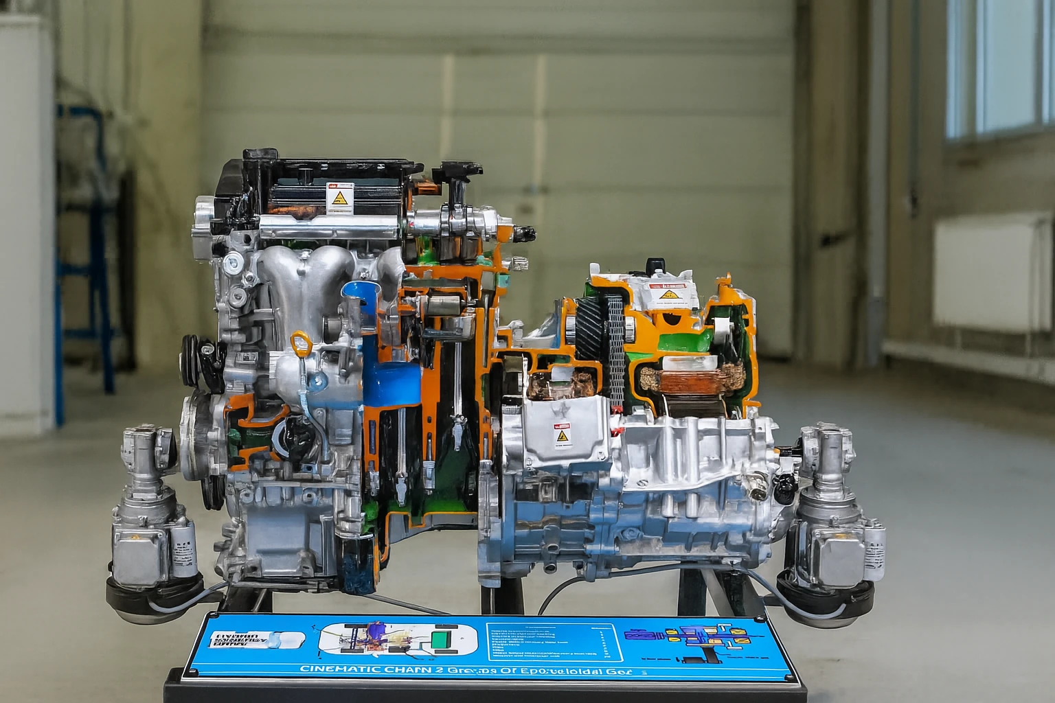
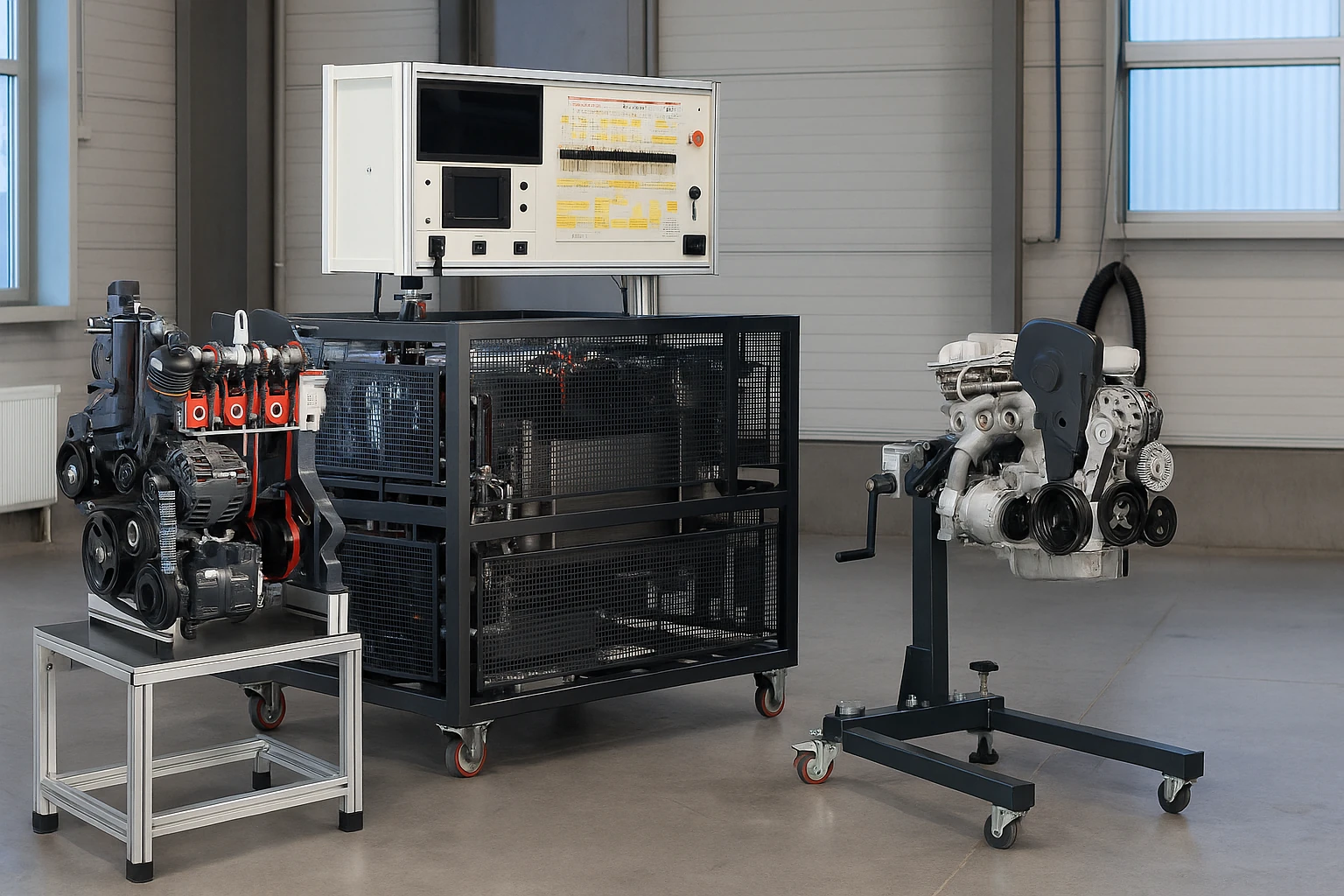
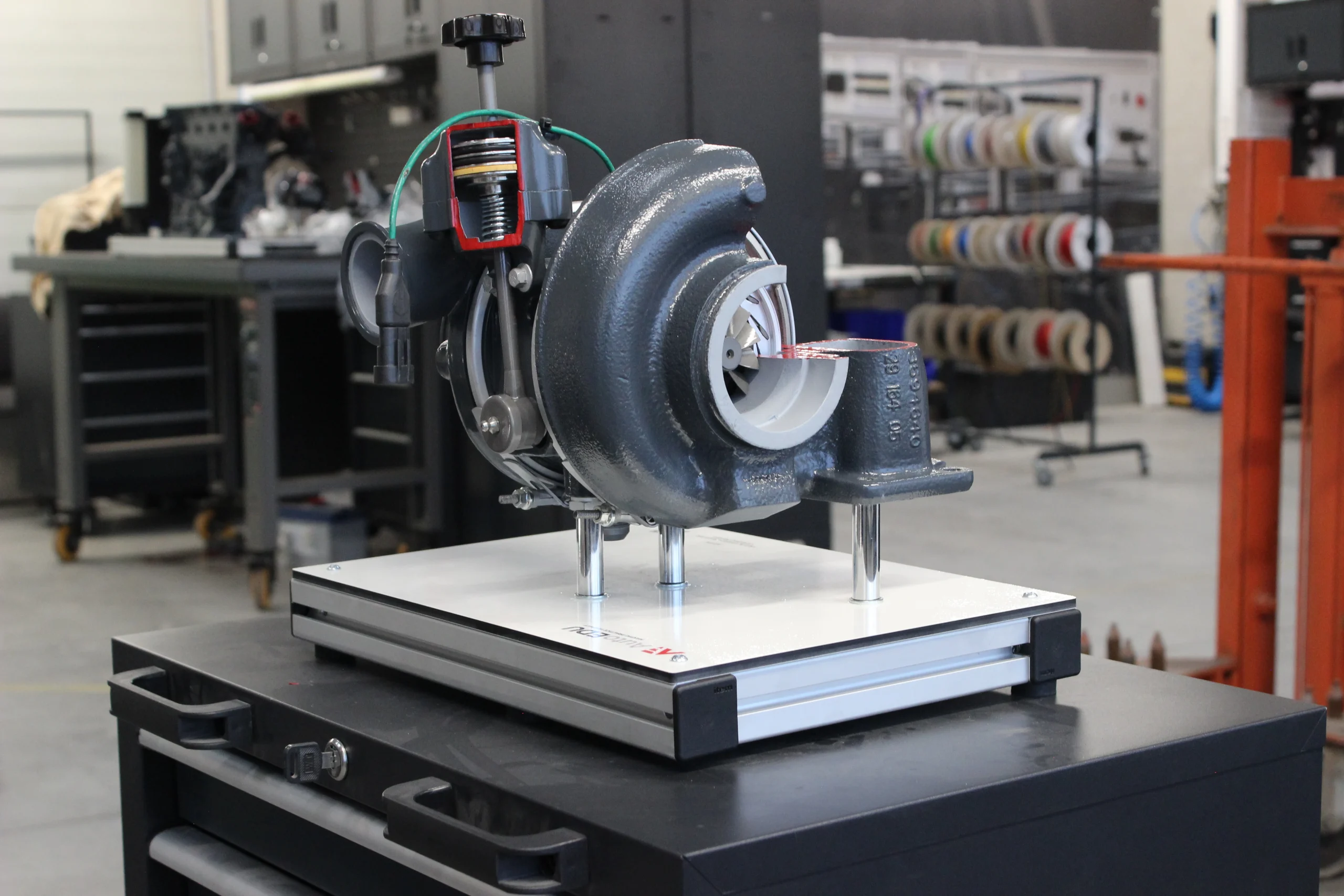
Looking to teach or learn more about this system hands-on? AutoEDU offers complete training platforms that simulate real cylinder deactivation in modern engines.

You can find related products here!

Cylinder deactivation isn’t just a clever trick—it’s an important solution in today’s balance of performance, economy, and emissions. It brings together old-school mechanical knowledge and modern control systems. For future technicians, understanding how this system works—and how to service it—is a must.

AutoEDU’s training systems help bridge the gap between theory and hands-on experience, making sure students can explain, diagnose, and work with these systems in any shop.

Want a visual diagram or classroom handout version of this post? Just let us know—we’re here to support your learning goals.

Turbocharge or Supercharge: How Forced Induction Powers Up Your Engine

At AutoEDU, we’re all about understanding automotive systems through hands‑on learning. In this post, you’ll see how turbochargers and superchargers deliver more horsepower—and how to think like a technician evaluating performance upgrades.

What Is Forced Induction?

Both turbochargers and superchargers are types of forced induction systems—they boost engine power by compressing extra air into the cylinders before combustion. This allows more fuel to burn and delivers more horsepower per engine blast.

Superchargers: Instant Boost from the Crankshaft

A supercharger is mechanically driven—usually by a belt connected to the engine’s crankshaft or sometimes by an electric motor. As the engine runs, it spins the compressor and forces extra air into the intake manifold.

Pros:

  • Immediate throttle response with no lag.

  • Strong low-end torque—ideal for racing or performance driving.

  • Simple to install and reliable.

Cons:

  • It uses some engine power to drive the compressor.

  • Lower fuel efficiency since energy is used to power itself.

  • Belt and mechanical components require regular maintenance.

Turbochargers: Power from Exhaust Waste

A turbocharger uses energy from hot exhaust gases to spin a turbine that drives a compressor. That compressor pressurizes intake air and pushes it into the engine for more power.

Pros:

  • Uses “wasted” exhaust energy, so it boosts efficiency.

  • Allows smaller engines to produce big power—great for downsizing.

  • Better fuel economy under light use.

Cons:

  • Turbo lag: delay before boost kicks in at higher RPM.

  • More complex installation—requires oil lines, intercoolers, and tuning.

  • Produces heat and needs strong cooling and lubrication systems.

A Bit of History

The roots of forced induction date back to the 19th century. Early superchargers were based on air pumps used in industrial applications, such as the Roots blower patented in the 1860s. The first use of a mechanically driven compressor on an internal combustion engine came in the early 20th century, and by the 1920s, Mercedes-Benz was producing cars labeled “Kompressor” with supercharged engines for added power.

Turbocharging was pioneered by Alfred Büchi, a Swiss engineer, who patented the concept in 1905. He envisioned using exhaust gases to drive a turbine that would compress intake air. Turbochargers became widely used in marine and aircraft engines in the 1920s and 1930s, especially for increasing performance at high altitudes. Passenger cars began to adopt turbocharging more broadly in the 1980s, with manufacturers looking to extract more performance and fuel efficiency from smaller engines.

Choosing Between Turbo and Super

Fuel efficiency and emissions regulations have driven automakers to favor turbochargers, especially in compact, fuel-efficient engines. Turbocharged inline‑4 and inline‑6 engines now replace larger, naturally aspirated V‑6s and V‑8s in many models.

Still, some high-performance vehicles benefit from superchargers’ instant response. Manufacturers like Mercedes-AMG have even introduced electric superchargers paired with turbos to eliminate lag and optimize power delivery across the RPM range.

Real‑World Technician Insights

At AutoEDU, we train students to diagnose and understand forced induction systems, including:

  • Recognizing boost delivery and throttle response differences

  • Inspecting oil and cooling system requirements for turbos

  • Checking belts, drive components, and pulley alignment on superchargers

  • Using dyno or scan tools to evaluate boost pressure and performance

Hands‑on experience with both turbos and superchargers gives students the confidence to understand why certain systems are used—and how to maintain and troubleshoot them effectively.

Summary Table

Feature Turbocharger Supercharger
Source of boost Exhaust gas turbine Belt/electric motor driven
Boost response Delayed (lag at low RPM) Instant, no lag
Efficiency High (uses waste energy) Lower (draws engine power)
Installation Complex — needs oil/cooling lines Simpler, bolt‑on style
Maintenance impact Requires cooling/oil checks Mechanical/belt system upkeep

Understanding forced induction isn’t just about recognizing a turbo or a supercharger. It’s about knowing how and why engineers choose one over the other—balancing performance, response, efficiency, and cost.

At AutoEDU, our training helps students explore both systems hands-on, preparing them to handle diagnostics and performance analysis in real-world vehicles. Whether boosting efficiency or chasing horsepower, knowing the “how” and “why” makes all the difference.

How Electricity Actually Works

Electricity can seem complicated at first—but when you break it down into smaller concepts and pair them with real-world examples, it becomes something you can truly understand and apply. At AutoEDU, we specialize in turning complex systems into hands-on learning opportunities. In this post, we’ll guide you through the basics of electricity in a way that’s practical, visual, and simple to grasp.

Why Electricity Matters in Automotive Training

Whether you’re starting your career in auto repair or diving into hybrid and EV systems, understanding electricity is non-negotiable. Every modern vehicle relies on electrical energy—not just for starting or lighting, but also for powering sensors, computers, fuel injection, infotainment systems, and more.

Electricity is a form of energy that powers systems by converting into:

  • Light (bulbs, indicators)

  • Heat (defrosters, resistors)

  • Motion (motors, actuators)

  • Magnetic fields (relays, solenoids)

Understanding electricity is key to troubleshooting issues, safely working on high-voltage systems, and becoming confident with advanced diagnostic tools. At AutoEDU, we want students not just to know that electricity works, but to understand how and why it works the way it does.

How Electricity Works: Atoms and Electrons

To understand electricity, you have to zoom in—way in—down to the atomic level.

All matter is made of atoms, and atoms are made of:

  • A nucleus (protons with positive charge and neutrons with no charge)

  • Electrons (negatively charged particles orbiting the nucleus)

The electrons in the outermost layer, called the valence shell, determine how easily an atom gives up or holds onto its electrons. The Bohr model shows electrons orbiting like planets around a sun. While simplified, this model helps students visualize how electrons can move between atoms.

Electricity is the movement of these free electrons from one atom to another. When enough atoms allow this kind of flow, we have a material that conducts electricity.

Free Electrons and Conductivity

Atoms with 1 to 3 electrons in their outer shell tend to lose those electrons easily. These free-moving electrons are what allow a material to conduct electricity. Materials made of these types of atoms are called conductors. Examples:

  • Copper

  • Aluminum

  • Silver

  • Gold

On the flip side, atoms with 5 or more valence electrons hold onto them tightly. These atoms don’t allow electrons to move freely and therefore act as insulators. Examples:

  • Rubber

  • Glass

  • Plastic

In between these extremes, there are semiconductors, like silicon, used in computer chips and sensors, which can conduct under the right conditions.

Understanding conductivity is critical for knowing which materials can safely carry electricity and which can safely block it.

Visualizing Electricity: The “Rubber Band Effect”

Let’s use an analogy. Imagine stretching a rubber band. The more you stretch it, the more energy you store. When you let it go, it snaps back with force.

Electricity works in a similar way. When electrons are removed from atoms and forced to one side—say onto the negative terminal of a battery—they create an imbalance. That imbalance wants to resolve itself. Electrons want to return to the “holes” or empty spots they left behind. This natural pull is called voltage, or electrical potential.

The more electrons you displace (or the further you “stretch the band”), the more voltage you create. Once a pathway is available (like a wire), the electrons rush back to restore balance—just like the rubber band snapping back to its original shape.

Electrical Current: Flowing Electrons

Now that we’ve built up voltage, we can talk about current. Electrical current is the flow of electrons through a conductor. It’s like water flowing through a hose, except it’s electrons flowing through copper wire.

There are two important factors in current:

1. How Many Electrons Move

This refers to the quantity of electrons passing through a given point in the circuit per second. Current is measured in amperes (A). One ampere equals 6.24 × 10¹⁸ electrons flowing past a single point every second. That’s a huge number—and it shows how small and fast electrons are.

2. How Fast They’re Moving

The speed at which electrons move depends on the voltage, or the “pressure” behind the flow. The more voltage you apply, the faster the electrons move. Just like higher water pressure causes faster flow in a hose, higher voltage causes more current flow through a circuit.

From Negative to Positive: Understanding Electron Flow

Electrons have a negative charge, and like charges repel each other. This is why electrons naturally move away from negative areas (high concentration of electrons) and head toward positive areas (which have fewer electrons or “holes”).

So in a DC (direct current) system like a battery:

  • The negative terminal is where excess electrons are stored.

  • The positive terminal is missing electrons.

  • When a wire connects both terminals, electrons flow from negative to positive, filling in the empty spaces and generating current.

This flow continues until balance is restored or the power source is disconnected.

Why Relating Theory to Real Demonstrations Matters

Knowing the theory is important—but it’s not enough. At AutoEDU, we believe in learning by doing. That means setting up real circuits, using DVOMs, lighting LEDs, and testing voltages. Why?

Because students need to:

  • See how electricity flows.

  • Measure current and voltage safely.

  • Connect concepts like “voltage” and “resistance” to real results.

  • Understand why things fail—like what happens if a conductor breaks, or if resistance is too high.

The point is to make electricity less of a mystery and more of a practical tool. When students can relate the invisible world of electrons to real-world systems, they build the confidence to diagnose and repair complex electrical systems.

Understanding electricity doesn’t have to be hard. Start with atoms. Understand electron flow. Visualize voltage like stretching a rubber band. Build circuits. Measure what happens. And most importantly—relate it back to real vehicles.

At AutoEDU, we’re committed to making automotive electricity clear, safe, and useful for every student. Whether you’re new to the trade or just want to sharpen your skills, Part 1 of this series is your first step into the world of modern electrical systems.

Understanding the Principles of Electricity: A Hands-On Approach for Future Technicians

At AutoEDU, we believe the best way to learn about electricity isn’t just by reading about it—it’s by seeing it, testing it, and experiencing it. That’s why our training programs are designed to help students connect classroom theory to real-world automotive systems using practical demonstrations and easy-to-understand explanations.

What Is Electrical Current?

Electric current is the movement of electrons through a conductor. It’s measured in amperes (A). One ampere means approximately 6.24 × 10¹⁸ electrons pass a single point in a circuit every second. This quantity of charge is called a coulomb, named after the French physicist Charles-Augustin de Coulomb.

While we can’t see electrons with the naked eye, their effects are very noticeable. We feel heat from wires, see light from bulbs, and observe electromagnetic forces in motors. Tools like digital volt-ohm meters (DVOMs) and oscilloscopes allow us to measure and analyze these movements precisely.

Understanding Voltage with the Rubber Band Analogy

Voltage is the potential force that drives electrons to move, and it’s measured in volts (V), named after Alessandro Volta. Imagine stretching a rubber band. The more you stretch it, the more potential energy it stores. When you let go, the energy is released.

A battery works in a similar way. Electrons are pushed away from one battery plate and gathered on another, creating an imbalance. This imbalance builds up electrical pressure—voltage. The plate with more electrons becomes the negative terminal, and the plate that has lost electrons becomes the positive terminal. When the two terminals are connected through a conductor, the electrons naturally flow back to their original position. This is called direct current (DC), where electrons flow in one direction.

Resistance and Electron Flow

As electrons flow, they don’t move freely without opposition. This opposition is called electrical resistance, measured in ohms, and named after Georg Simon Ohm. Resistance depends on several factors: the type of material, its temperature, length, and cross-sectional size.

Materials like copper, silver, and aluminum allow electrons to pass easily and are known as conductors. Insulators like rubber or plastic have tightly bound electrons that resist flow. However, if the voltage is high enough—as in the case of lightning—it can overcome even the resistance of air.

Bringing Concepts to Life: The Fruit Battery Experiment

To demonstrate electricity in a simple and memorable way, we use an experiment with everyday items. Students insert a brass screw and a galvanized screw into a lemon or potato, then use a DVOM to measure the voltage. This basic setup produces around 600 to 1,000 millivolts. Connecting an LED allows students to see the electrons flowing and lighting the diode.

By switching the DVOM leads, students can identify the polarity of each screw and see which one becomes the negative terminal. If multiple lemon or potato batteries are connected in series—positive to negative—the total voltage increases. This fun, visual activity helps students understand voltage, polarity, chemical reactions, and electron flow.

Charging and Discharging a Battery

Just like stretching and releasing a rubber band, a battery can be charged and discharged. When electrons return to their original positions, the battery is considered discharged or “dead.” Charging the battery pushes electrons back to their previous plates, building voltage again. However, just like a rubber band weakens after repeated use, batteries degrade with time and usage.

Electrical Power and Why It Matters

Power is the rate at which electrical work is done. It’s calculated using the formula:
Power (Watts) = Voltage (Volts) × Current (Amps).

Power ratings are critical in automotive systems. A device’s ability to function without overheating depends on matching its power rating to the current and voltage it receives. For example, if students connect three resistors with the same resistance but different power ratings, they’ll see that the lowest-rated one may burn out, while the highest-rated one remains cool—even under the same electrical load. This helps them grasp how power affects performance and safety in real systems like starter motors, alternators, and audio equipment.

Building a Strong Foundation

By the end of these lessons, students understand much more than just theory. They can explain how electricity works, where electrons come from, and why a battery charges or dies. They know how to use Ohm’s Law to calculate current, voltage, resistance, and power, and they recognize how these principles apply to the vehicles and devices they’ll work with in the future.

At AutoEDU, we make sure students don’t just memorize—they experience. Our hands-on training connects the dots between textbooks and real-world diagnostics, setting the stage for confident, competent automotive technicians.

Explained: Induction Motors vs. DC Brushless Motors in Automotive Systems

Electric motors are everywhere in modern vehicles, powering everything from main drive systems to small accessories. The two most common types in automotive use are induction motors and DC brushless (BLDC) motors. Both convert electrical energy into mechanical movement, but their designs and performance are different. Understanding these differences is essential for anyone working with automotive technology or pursuing technical training.

Induction Motors: Principles and Applications

Induction motors, also known as asynchronous motors, are valued for their simplicity and reliability. Their main parts are the stator, which holds the wire windings, and the rotor, which is made of steel laminations and conductive bars.

When AC power flows through the stator, it creates a rotating magnetic field. This field induces current in the rotor without any physical electrical connection. The interaction between the induced rotor current and the stator’s magnetic field produces torque, which turns the rotor.

Induction motors are highly durable and need little maintenance since they have no brushes or commutators. Their speed depends on the AC supply frequency and the motor’s design. In automotive systems, induction motors are common in electric vehicle traction drives, HVAC blowers, and various electric pumps. They are chosen where simple, robust, and reliable power is needed.

DC Brushless Motors (BLDC): Principles and Applications

DC brushless motors work differently. They use a permanent magnet rotor and an electronically controlled stator. Sensors, usually Hall-effect, monitor the rotor position so the controller can switch current to the correct stator windings. This electronic commutation leads to high efficiency and very precise speed and torque control.

Because there are no brushes, BLDC motors require minimal maintenance and are quiet with low vibration. They are widely used in electric power steering, cooling fans, electric window lifters, and many electronic accessories in modern vehicles. BLDC motors are ideal where precise, efficient, and reliable control is required, even in compact spaces.

Where These Motors Are Most Commonly Used

Induction Motors:

  • Main electric drive systems in electric vehicles (EVs), especially in larger or older EV models.

  • Industrial automotive equipment such as lifts, compressors, and heavy-duty pumps.

  • HVAC blowers and coolant pumps in commercial and specialty vehicles.

DC Brushless Motors (BLDC):

  • Electric power steering systems, due to the need for responsive and smooth control.

  • Cooling fans for engines and batteries, which benefit from variable speed operation.

  • Electric windows, seat adjusters, and sunroof drives.

  • Hybrid and newer electric vehicle propulsion systems, where high efficiency and compact design are critical.

Why It Is Important to Understand the Differences

Understanding the differences between induction and BLDC motors is crucial for several reasons:

  • Correct Motor Selection: Each motor type is suited for specific automotive tasks. Using the wrong motor can lead to inefficiency, higher costs, or mechanical failure.

  • Effective Troubleshooting: Diagnosis and repair procedures differ between motor types. Knowing how each operates ensures accurate and efficient maintenance.

  • Advancing Technology: Automotive technology is evolving rapidly. New vehicles increasingly use BLDC motors for advanced features, while some systems still rely on the robustness of induction motors.

  • Training and Safety: Handling and servicing electric motors requires technical knowledge. Awareness of motor types and their control systems is essential for safety and professional development.

Get the Best in Automotive Education
Get in Touch
Contacts
Newsletter
© 2025 AutoEDU. All rights reserved
Privacy Policy